Here are a few videos related to cripple wall retrofits. A textual description below the videos may be all you need.
This 50 minute video has more than you will ever want to know.
THIS 10 MINUTE VIDEO GIVES YOU THE BASICS.
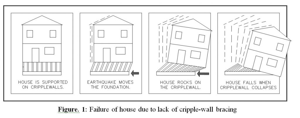
This is why seismic retrofits work
This is what earthquake damage looks like.
BASIC CRIPPLE WALL ENGINEERING.
The Basics of Cripple Wall Retrofits
The most common seismic retrofits are cripple wall retrofits. Unlike most other home improvement projects, they should be designed using the engineering calculations behind Standard Plan A. In the event you have less than 3 steps leading into the house, you probably need a no cripple wall retrofit should study the material on that web page.
Cripple Wall Retrofits in Three Simple Steps
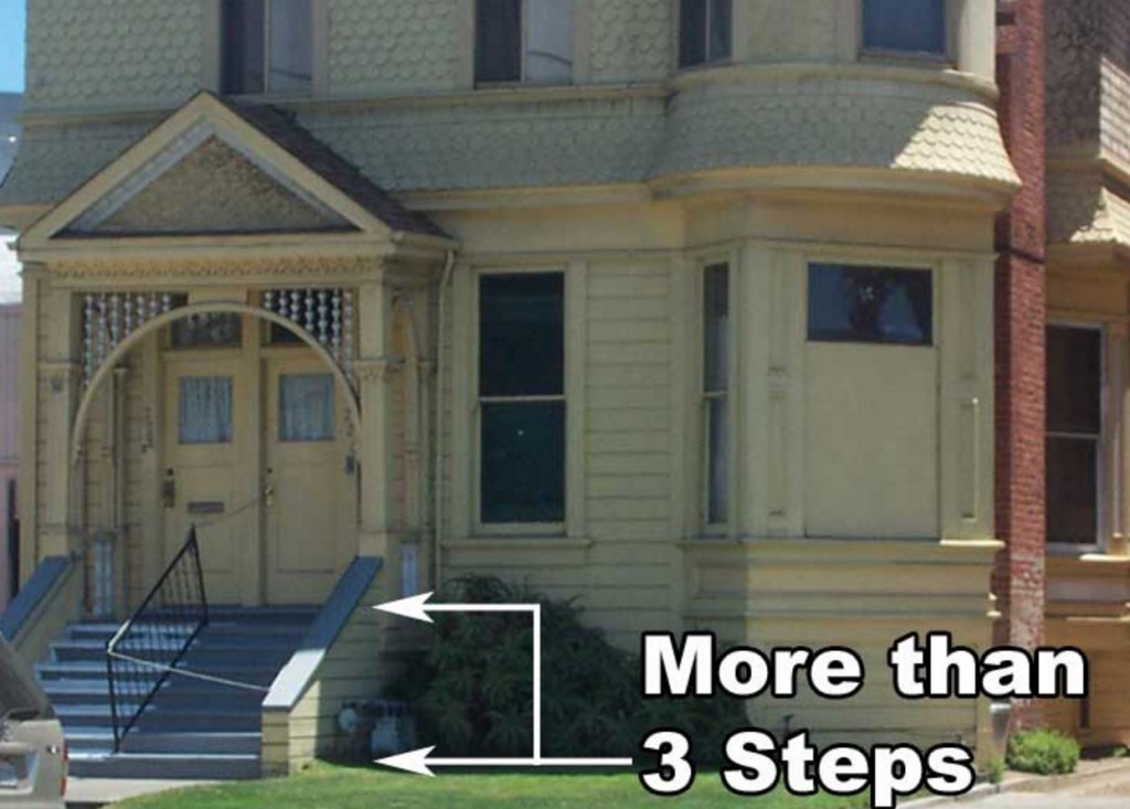
THIS IS A GOOD EXAMPLE OF A CRIPPLE WALL. IF YOU HAVE MORE THAT 3 STEPS LEADING INTO YOUR FRONT DOOR, YOU PROBABLY HAVE A CRIPPLE WALL AND NEED A SEISMIC RETROFIT

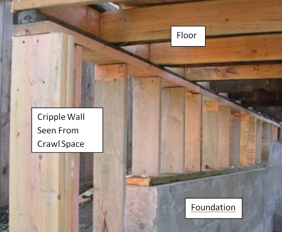
A TYPICAL CRIPPLE WALL.
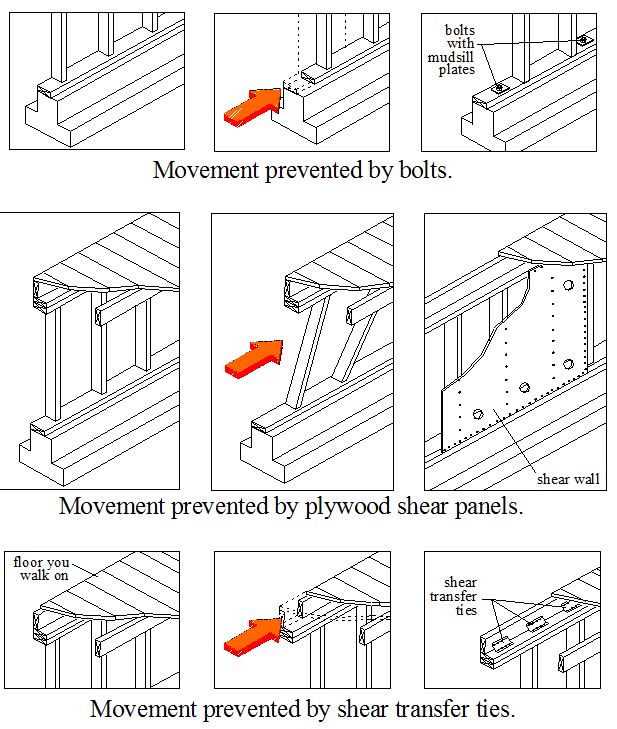
The Mechanics of Cripple Wall Retrofits
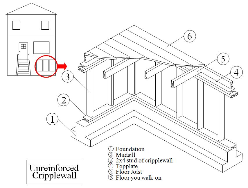
THIS ILLUSTRATION SHOWS ALL THE AREAS WHERE A SEISMIC RETROFIT MIGHT FAIL.
CRIPPLE WALL FAILURE: All the parts of a cripple wall. As you can see, each component connects to component part, much like the links in a chain. Accordingly, a retrofit strengthens all the connections in a cripple wall.
THE AUTHOR INSPECTED THIS HOUSE WHILE WORKING FOR FEMA. ALTOGETHER, HALF THE HOUSES ON THIS BLOCK FAILED LIKE THIS.
Step 1: The Plywood Connection
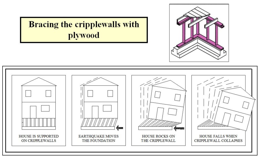
The illustration below shows how plywood in cripple wall retrofits keeps the cripple wall from collapsing. While there are many types of plywood, only one type resists earthquakes effectively. In addition, the size and spacing of the nails and the type of cripple wall framing impact the earthquake resistance of the plywood. This video describes how plywood prevents cripple wall collapse.


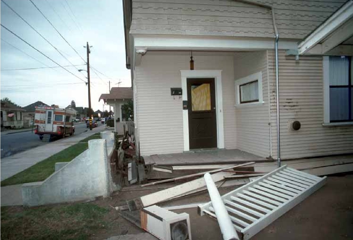
The author was the FEMA inspector who evaluated this beautiful Watsonville home after the 1989 San Francisco Earthquake. Two weeks after the evaluation, I drove by and saw an empty lot.

HERE IS A TYPICAL EXAMPLE OF A CRIPPLE WALL COLLAPSE.
Earthquakes knock houses off their foundations. Damage to interior walls, plumbing, and electrical systems is catastrophic.

Cripple Wall Retrofit Need Foundation Bolts
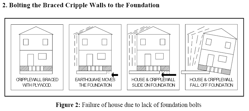

THE RED ARROW SHOWS HOW EARTHQUAKE FORCES PUSH AGAINST THE BOTTOM OF THE CRIPPLE WALL. RETROFIT FOUNDATION BOLTS COUNTERACT THIS FORCE.
Bolts provide a counter force against earthquake forces
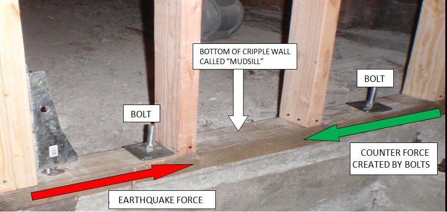
BOLT RESISTING EARTHQUAKE FORCE BY CREATING A COUNTER FORCE OR RESISTANCE.
Types of Retrofit Foundation Bolts
There are a few types of retrofit foundation bolts: epoxy bolts, wedge anchors, and screw anchors. They bolt the base of the mudsill to the foundation.
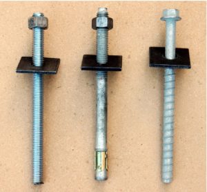
FROM LEFT TO RIGHT, EPOXY BOLT, WEDGE ANCHOR BOLT, AND TITEN BOLT
The Importance of Plate Washers
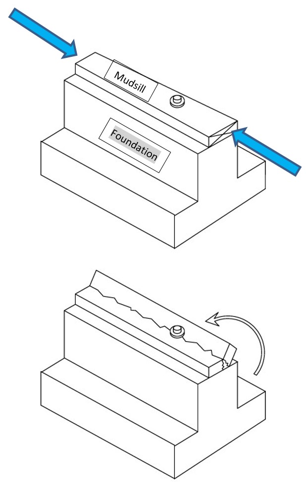
Earthquake forces represented by the blue arrows resist a tremendous amount of earthquake force before the wood will fail. In contrast, wood fails quickly when put in a state called “Cross Grain Bending.” First and foremost, plate washers prevent this.
CROSS-GRAIN BENDING IS SOMETHING WOOD CANNOT RESIST WITHOUT SERIOUS DAMAGE.
Cripple Wall Retrofits Convert Cripple Walls into Shear Walls
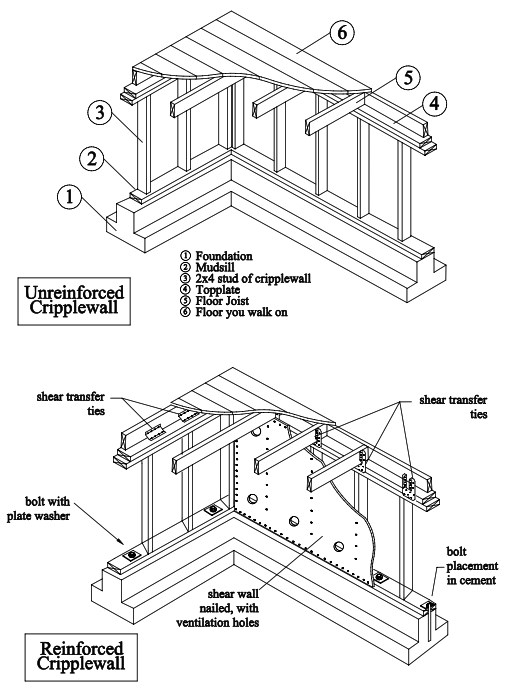
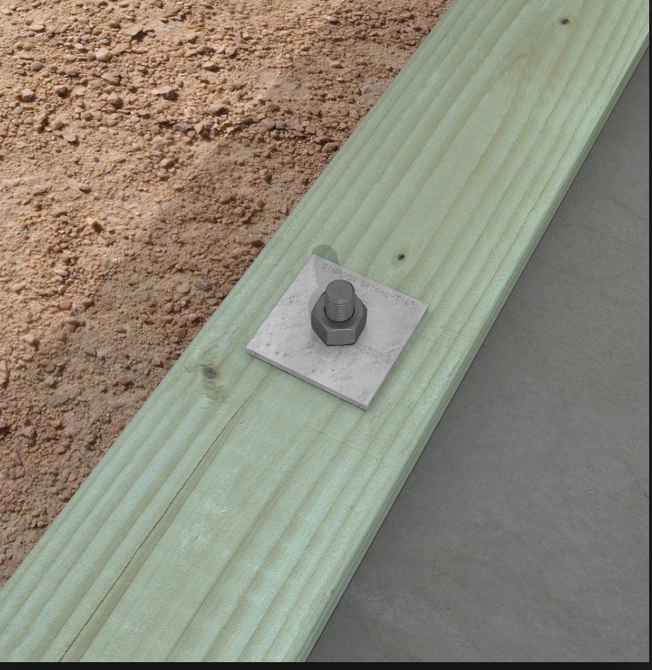
PLATE WASHERS RESIST CROSS GRAIN BENDING.
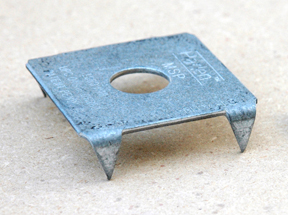
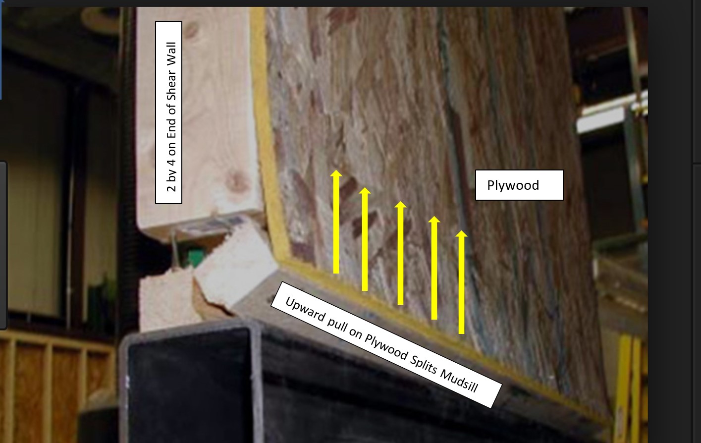
DAMAGE CAUSED IN THE BOLT TO WOOD MUDSILL CONNECTION SPARKED THE DEVELOPMENT OF THIS HARDWARE.
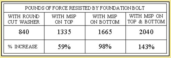
THIS HARDWARE CAN INCREASE FOUNDATION BOLT STRENGTH BY 143% AND REDUCES SPLITTING.
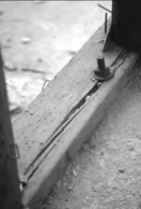
The photo above shows a split mudsill. Notice how the washer is small and round and not large and square.
Below is a photograph of a shear wall where vertical bolt drilling equipment is too tall to install standard bolts. For this reason, foundation anchors bolt the plywood and mudsill to the side of the foundation. Plywood and shear transfer tie installations remain the same.
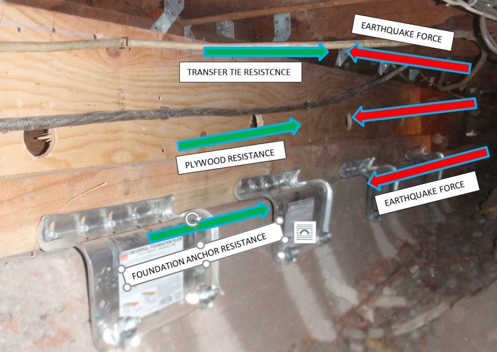
PLYWOOD AND OTHER COMPONENTS RESISTING EARTHQUAKES.
How Plywood Does its Job
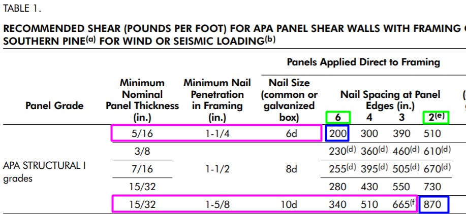
The building code rates plywood in terms of how much earthquake force it can resist. For example, if a potential earthquake strikes a house with 10,000 lbs. of force, obviously the plywood must also resist 10,000 lbs. of earthquake force. The table below tells us how many linear of feet of plywood resist that much force. The type of plywood, size of nails, and nail spacing determine the earthquake resistance of shear walls.
Step Three: Shear Transfer Ties in Cripple Wall Retrofits
Houses with balloon framing do not use shear transfer ties.
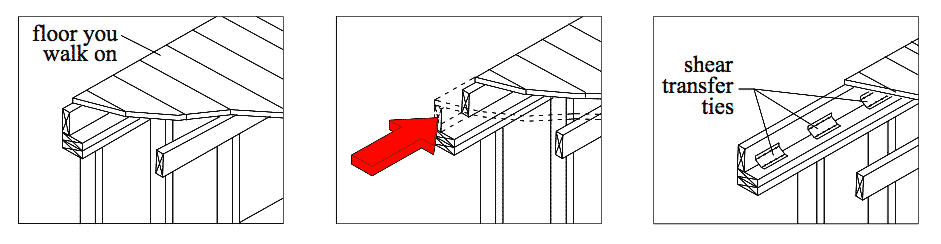
Figure 3 shows a cripple wall bolted to the foundation with plywood on it. Shear Transfer Ties prevent the floor from sliding on top of the bolted and plywood braced cripple wall. Shear transfer ties attach the floor to the cripple wall. This is the final stage of a cripple wall to shear wall conversion.

THIS HOUSE SLID OFF THE BOLTED AND PLYWOOD BRACED CRIPPLE WALLS. SHEAR TRANSFER TIES CONNECT THE FLOOR TO THE BRACED CRIPPLE WALL.
All seismic retrofit guidelines require the installation of shear transfer ties. Be sure to use the right one- many shear transfer ties on the market don’t do anything at all in terms of earthquake resistance.
THESE SHEAR TRANSFER TIES RESIST EARTHQUAKE MOVEMENT. THESE ARE VITAL TO ANY EFFECTIVE WOOD FRAME HOME RETROFIT.
Below is one kind of Shear Transfer Tie- there are many others.
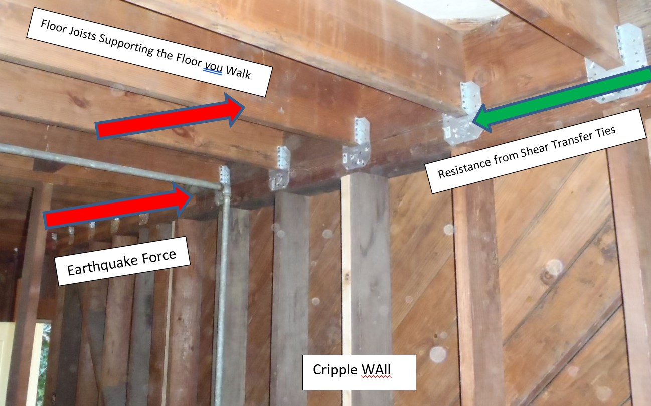
SHEAR TRANSFER TIES RESISTING THE EARTHQUAKE FORCE.
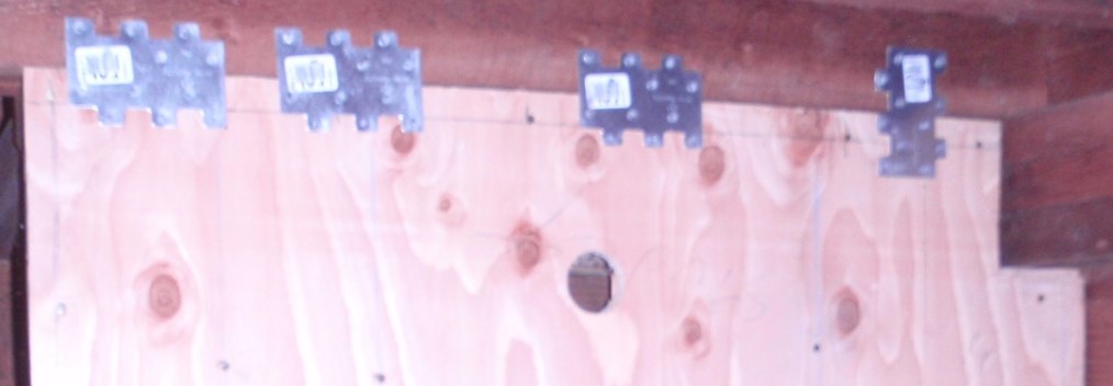
ANOTHER TYPE OF SHEAR TRANSFER TIE.
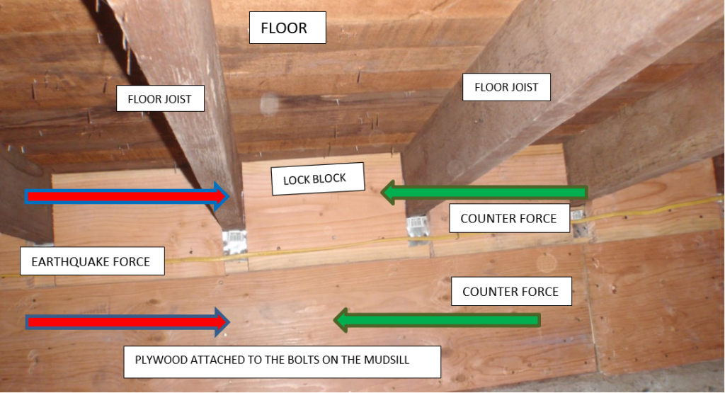
SHEAR TRANSFER TIES MADE OF “LOCK BLOCK” 1 and 1/8 ” PLYWOOD.
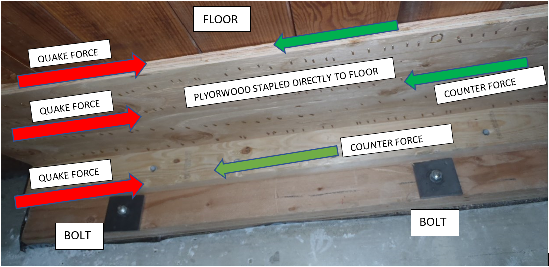
PLYWOOD STAPLED DIRECTLY TO THE FLOOR DOES THE SAME THING AS A SHEAR TRANSFER TIE.
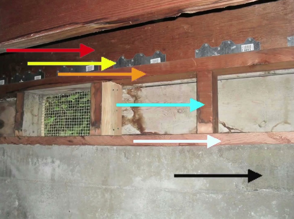
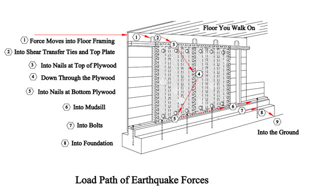
Load Path of Earthquakes
RED ARROW – force trying to slide floor joist off of cripple wall.
YELLOW ARROW – sliding of joist prevented by shear transfer ties.
ORANGE ARROW – force pushing on top of cripple wall through shear transfer tie.
BLUE ARROW – movement of top plate prevented by plywood, this image is before plywood installation (plywood prevents cripple wall from collapsing).
WHITE ARROW – Force trying to slide mudsill off foundation. Attaching the mudsill to the foundation prevents this.
BLACK ARROW – Force absorbed by foundation and transferred into ground.
Review of the Three Steps in a Cripple Wall Retrofit
ALL THESE RETROFIT COMPONENTS WORK TOGETHER TO TRANSFER FORCES INTO THE FOUNDATION.
The Three Parts of a Cripple Wall Retrofit Work Together
The Shear Transfer Ties, Plywood, and Bolts work together to transfer the side-to-side Motion of an Earthquake into the Foundation and into the Ground. This is called the Load Path. If any component within the load path chain is missing or weak, the retrofit will fail.
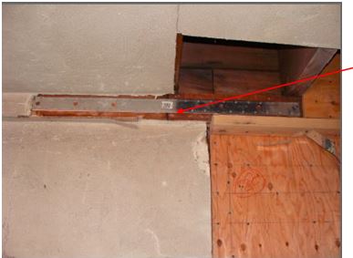
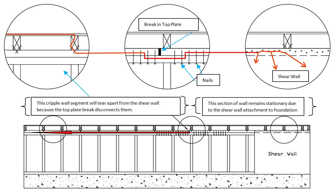
Addressing Breaks in the Top Plates
Contractors call the horizontal board on top of the cripple wall the upper top plate. All the earthquake forces transfer from the floor into the upper top plate. Joining all the upper top plate sections together attaches the entire top plate to the shear wall and is extremely necessary for an effective retrofit.
When building a house, contractors butt together 2 by 4’s, eight to 24 feet to create an upper top plate. Seismic retrofit designers call the point where these 2 by 4s butt together a break in continuity. Earthquake forces concentrate in these breaks and will not allow earthquake forces to be resisted by the shear wall. Please see the illustration below and watch the video.

Seismic retrofit contractors address breaking in upper top plate continuity in two ways, namely steel straps or nails. In the image below, a steel strap called a CST strap connect two sections of the top plate. The break in the top plate is shown by the red arrow.
Contractors also do this with nails

Connecting the Plywood to the Mudsill
The Problem

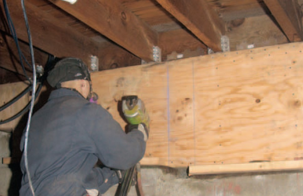
The largest national shear wall research laboratory in the world evaluated the 4 possible methods of attaching the plywood to the mudsill: the Nailed Blocking Method, the Stapled Blocking Method, the Reverse Blocking Method, and the Flush Cut Method. They found the flush cut method most closely matches their tested systems. This video: The Retrofit Mudsill Connection looks at these methods in great detail.

The illustration shows the plywood nailed flush cut mudsill and cripple wall.
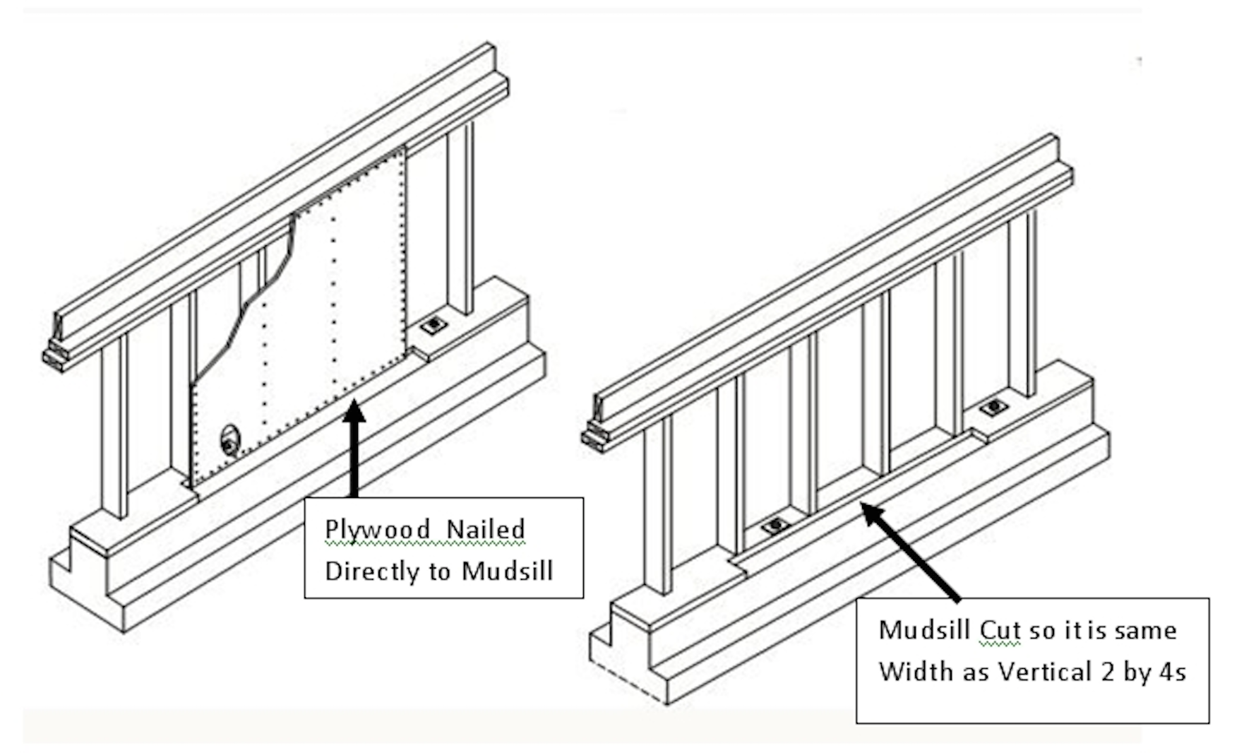
Nails do not easily split old growth redwood compared to tree farm wood.


- A 2 by 4 is placed along the long edge of a piece of plywood.
- The plywood has been nailed to the 2 by 4 from the back where you can’t see the nails.
- The 2 by 4 of this assembly is nailed to the top of the mudsill and along all edges.

NAILING REVERSE BLOCK SHEAR WALL ONTO MUDSILL.

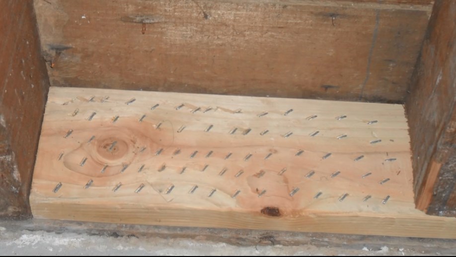

STAPLED BLOCK WITH STRENGTH OF 80 NAILS AND NO SPLITTING.
The Nailed Blocking Method

ON THE LEFT, A CONTRACTOR NAILED 2 BY 4 BLOCKS ONTO THE MUDSILL. ON THE RIGHT, HE NAILED THE PLYWOOD TO THE SIDE OF THE BLOCKS.

HERE IS A CONTRACTOR NAILING 2 BY 4 BLOCKS ONTO THE MUDSILL
Why are Blocks a Problem?
This method often splits the blocks. If the blocks split, then the shear wall will fail. When the blocks split, it is quite tempting for the installer to leave those split blocks in place because of the time and labor involved in removing them. Seismic retrofit contractors often believe “the more and bigger the nails, the better” which makes the problem worse.

BLOCK SPLIT DURING AN INSTALLATION.

SPLIT BLOCK WILL NOT PERFORM AS INTENDED.

Once the contractor nails the plywood to the cripple wall it is impossible to see the blocks. Thereafter no one will know the condition of the blocks.
The Whole House Does Not Need a Seismic Retrofit
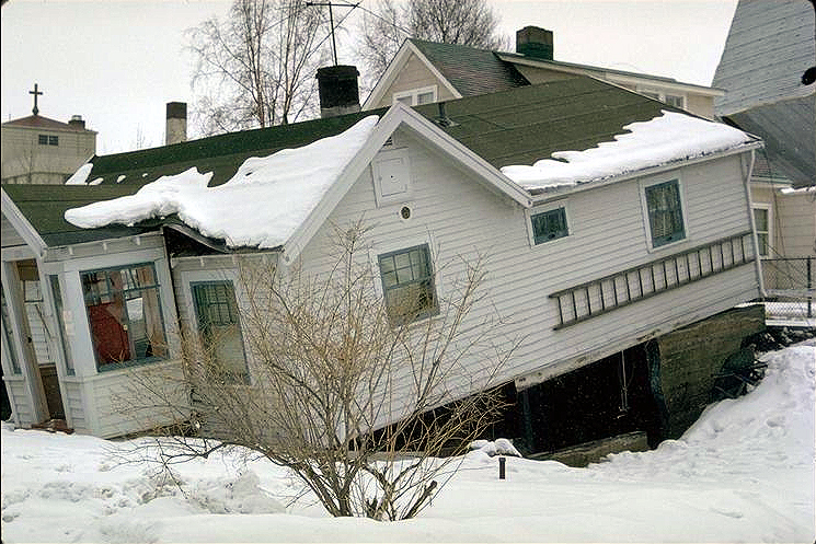
There is a misconception that a seismic retrofit involves work which is over and beyond attaching the floor to the foundation. In particular including the living area above the first floor that you walk on.
As you can see in this photograph, the house fell off its foundation several feet because of a cripple wall collapse, but otherwise remained intact. Notice how the windows are not even broken. Retrofits save houses like this by attaching them firmly to the foundation with a cripple wall retrofit.
Why so little earthquake damage?
The house itself, as well as all the rooms in the house, are all cubes and cubes are a very strong geometric shape. The honeycomb of cubes that are made of the hallways, bedrooms, bathrooms, kitchens, etc. prevent the collapse of the living area.
The author noticed this firsthand while working for FEMA. The cuboid shape of this house held it together so well that the windows did not even crack, illustrating the resistance of cubes to earthquake damage.

THIS HOUSE SLID OFF ITS FOUNDATION IN THE 1992 FERNDALE EARTHQUAKE DUE TO A CRIPPLE WALL COLLAPSE.
Same House: Earthquake Damage on the Inside
Houses that fall from their foundations sustain damage to interior walls, plumbing, and electrical systems which can be catastrophic.
Cripple Wall Retrofits Can Be Damaged by Overturning
Shear walls not only slide off the foundation, they also try and overturn or flip over. This is illustrated by the red rotating arrows below.

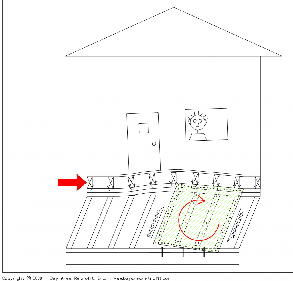
How to Resist Overturning
Overturning damages mostly tall narrow shear walls. Tall narrow walls act like a tall bookcase that will flip over if someone tries to push it across the floor from the top. On the other hand, a short wide bookcase will not have this tendency; it will simply slide on the floor and not try to flip over or overturn. Therefore, hardware that resists overturning, called hold-downs, should only be used if an analysis shows they are tall and narrow enough to be necessary. The photo below illustrates how tall narrow walls on either side of the garage door opening have overturned.

The illustration below shows the kind of damage that can occur when shear walls overturn.


The pink building on the left used to be two stories. The overturning of tall, narrow shear walls on either side of the garage causes this collapse.

Hold Downs Resist Overturning
The hold-down hardware shown at the ends of the shear wall in the figure above are designed to resist overturning forces. One hold down is installed at each end.
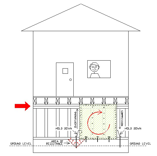
When earthquake forces push on the shear wall as shown by the red arrow, the left end of the shear wall pulls up on the hold-down. The hold-down pulls up on the hold-down bolt, which in turn pulls up on the foundation. When the earthquake changes directions, the exact same thing happens, but in the other direction.
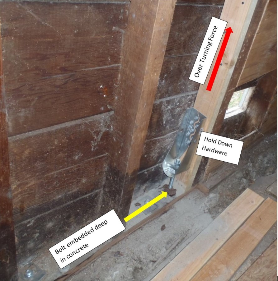

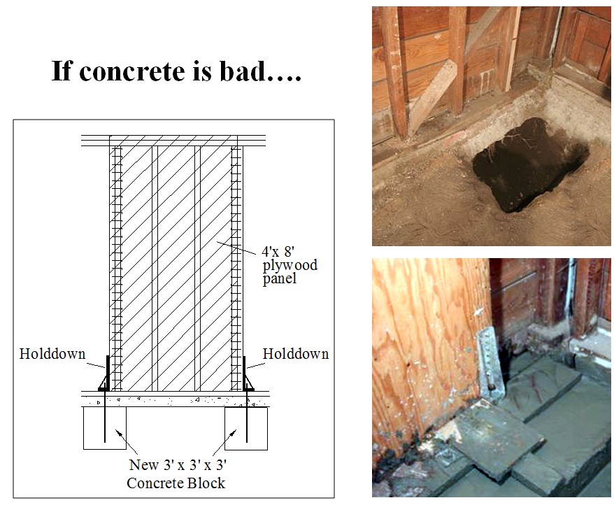
Sometimes the overturning forces are so great that an un-reinforced concrete foundation breaks.
Getting New Concrete Under the Hold Downs
If you can afford it, the best solution to prevent overturning is to provide additional weight to anchor the hold-downs to. The existing un-reinforced concrete foundation shown here is only 8 inches deep and 12 inches wide. It is not heavy enough to resist the potential overturning forces.
How to Design a Cripple Wall Retrofit
Calculating the Amount of Materials Needed and where they go
Perhaps the most critical decision is knowing how many linear feet of plywood, how many bolts, and how many shear transfer ties a house needs, and where to put them. This is fully explained in this video.
Installing more than required can strain a budget; not doing enough can cause the seismic retrofit to fail. This is determined by using these engineering calculations.
Let’s use a theoretical example to illustrate a principle. Earthquake forces to be resisted at the base of the house (Foundation Level) will equal its weight (the engineering calculations tell us what that is) x 0.186 Gs as per the calculations mentioned above.
In our theoretical example we are using a weight of 80,000 lbs. and a G force of 0.2 Gs (we rounded 0.186 up for simplicity’s sake)
Example: We have a two-story house that measures 25 feet by 40 feet, or 1,000 square feet (25 x 40 = 1,000).
The first thing we do is figure out how much earthquake force is going to strike the house. Assume the engineering calculations for our theoretical two-story house weighs 80 pounds per square foot; to figure out how much this house weighs we simply multiply the square footage (1000 square feet) by the weight (80 pounds per square foot) or 80,000 pounds. Remember to use the calculations to figure out the actual weight, this is for educational purposes only.
Finally, we take the ground acceleration of 0.2 Gs and multiply it by 80,000 and the result is 16,000. That is the pounds of force that will strike the house.
Sample Design Used in Cripple Wall Retrofits
This house must have enough bolts to resist a minimum of 16,000 lbs. of force AND enough plywood on the cripple walls to resist a minimum of 16,000 lbs. of force AND enough shear transfer ties to resist the same 16,000 lbs.
Government recognized tests rate bolts, shear transfer ties, and types of plywood in their ability to resist earthquakes. These tests measure the retrofit component’s ability to resist earthquakes. For example, if tests show a bolt can resist 1,500 lbs. of force, clearly the bolt will fail when 1,600 lbs. of force push on the side of it.
In this example we need the bolts, plywood, and shear transfer ties to resist 16,000 lbs. of force.
 EARTHQUAKE FORCES ATTACKING A HOUSE.
Foundation Bolt Quantity
8,000 pounds of earthquake force is striking this house on each side. Let’s say our bolts can resist 1142 lbs. Divide 8,000 lbs. by 1142 lbs. and the answer is 7 bolts.

DETERMINING THE NUMBER OF BOLTS REQUIRED.
Linear Footage of Plywood Required
Cripple wall retrofits require plywood to prevent collapse. Let’s figure out how many linear feet of plywood we need. First thing we need to be aware of is that good quality plywood can resist 571 pounds of force. We that that, divide it into 8000 lbs. (the amount of force that will be attacking our house), and voila! we discover we need 14 linear feet of plywood. That’s it! We can now move on to shear transfer ties.

DETERMINING AMOUNT OF PLYWOOD NEEDED.

PLYWOOD PREVENTING A CRIPPLE WALL COLLAPSE.
Shear Transfer Tie Quantity
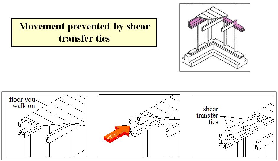
The required number of shear transfer ties used in cripple wall retrofits are figured out in the same method. Good shear transfer ties can resist approximately 600 pounds of earthquake force. 8,000 divided by 571 equals 14. We need this many shear transfer ties along each side of the house. The purpose of shear transfer ties is to prevent movement of the floor framing on the cripple wall top plate as illustrated below.
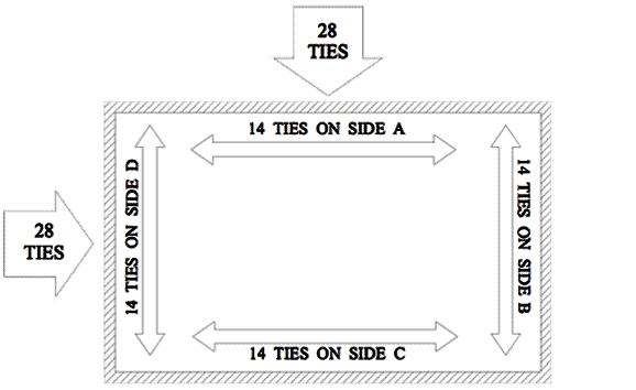
DETERMINING THE NUMBER OF SHEAR TRANSFER TIES NEEDED.
HOW SHEAR TRANSFER TIES WORK.

HERE ARE TWO TYPES OF SHEAR TRANSFER TIES, THERE ARE MANY MORE.
A complete cripple wall retrofit with bolts, plywood, and shear transfer ties looks like the image below. Be sure and notice the legend on the lower right.
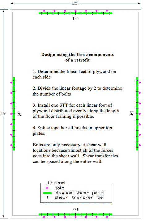
A COMPLETE RETROFIT WITH BOLTS, PLYWOOD, AND SHEAR TRANSFER TIES.

